

$553.00
Holiday Hours Notice: We will close at noon CT on Friday, May 22, resuming business on Tuesday, May 26. Orders placed after 11 AM CT on May 22 will be processed on May 26.
View full holiday schedule

Grid Connect can customize or produce a product based on our technology that fits your requirements.

Quickly and effectively implement your partial or complete, networking or embedded product.

We specialize in solving challenging IoT problems in demanding environments. No matter your application requirements.
SKU: GC-DK-MICROMOD-USB
MPN: IPEH-002079
Manufacturer: Peak System Technik
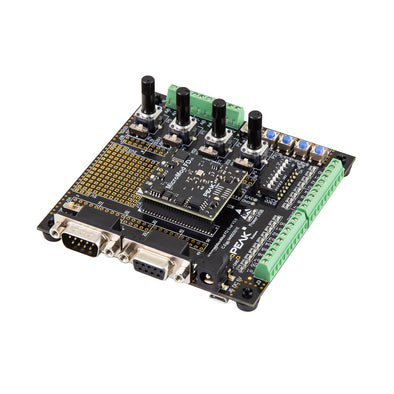
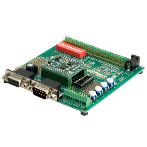
Develop your own CANbus Network! Everything you need to develop a CAN I/O Device interface, and network your device via CANbus to a PC.
Development Kit includes:
The MicroMod CPU is a small (32 x 36 mm) module for OEM designs, it requires a single regulated 5 VDC power supply. The integrated firmware allows for simple configuration of the module with the FREE Windows configuration software. No embedded programming skills are required. The configuration data is sent to the module via CAN. Up to 32 MicroMods can be integrated in a single CAN network. Each individual module can be addressed over the bus enabling to read, modify and store its configuration data.
SOFTWARE:
The included Windows software makes the following module configuration options available to the user: The digital input levels can send periodically or following a signal level transition (rising edge, falling edge or both transitions). Digital inputs can be logically connected (AND, OR, XOR, NAND, NOR, XNOR). The results are then displayed on the desired digital outputs and/or sent over the CAN bus. Analog values can be converted by Scale-value and Offset-value and then processed further. Adaptation of analog values is possible via characteristic curves. Direct conversion of analog inputs to CAN-IDs is supported. The rotary-switches (based on the rotary-encoder principle), which are standard in automotive applications, are supported directly.
CAN Download Support
View the available Peak System downloads:
MPN
IPEH-002079
$553.00
Please fill out the information below and our sales team will respond within 1 business day.
What you can expect from Grid Connect:
